The first piece of equipment I’ll be looking at is a Centrifuge. This will be required to separate cells from their media. Like most scientific equipment, there are many types of centrifuges, from the ridiculously expensive to the near useless. From the $20,000 Benchmark Z496-K to the $50 Chinese OEM 800-1. The latter includes instructions such as “Have a children’s environment use, should close attention.”
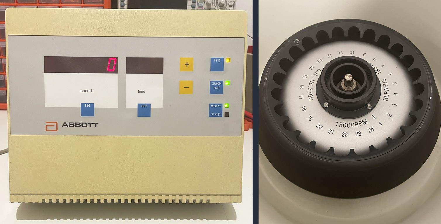
I already have an older model centrifuge, an Abbott Laboratories Biofuge 13, which I’ve had for some time. It is getting on a bit, over 25 years old, but it still works well and is incredibly well-built. However, the rotor it currently has only supports 1.5ml tubes, and we will need something much bigger. While it would be good to have the ability to use 50ml conical tubes, these machines are a lot more expensive. The next best option is a machine that handles 15ml tubes, which are more reasonably priced.
Given the options, I decided to modify the cheapest alternative, which is the 800-1. However, modifying is an understatement; there won’t be much left from the original device other than the case!
I purchased an 800-1 off eBay for $80, which was delivered within a few days. The unit promises adjustable speeds from 0 - 4000 RPMs (500 RPM intervals), a 0 - 60 minute timer and a 6 x 20ml rotor. The rotor has inserts that fit 15ml tubes or can be removed for 20ml ones. I won’t bother testing it because it doesn’t meet my requirements anyway. So, let’s take a look inside.
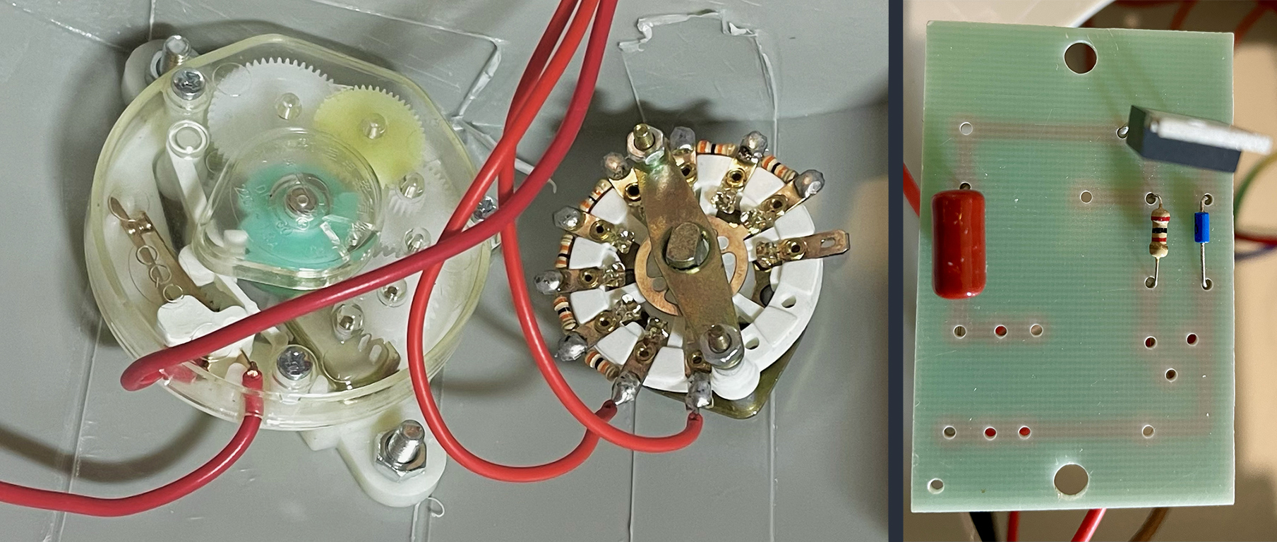
Firstly, the speed is controlled by a multi-position dial and a voltage divider network. Given the resistors are all the same value (30k ohms), there would appear to be no calibration. The timer is a plastic mechanical timer; I wasn’t expecting much more, given it was $80.
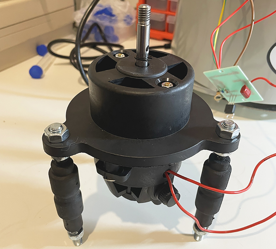
The motor is a basic open 240v brushed motor; again, it was nothing special. It does have a reasonable mount, with rubber legs to reduce vibrations.
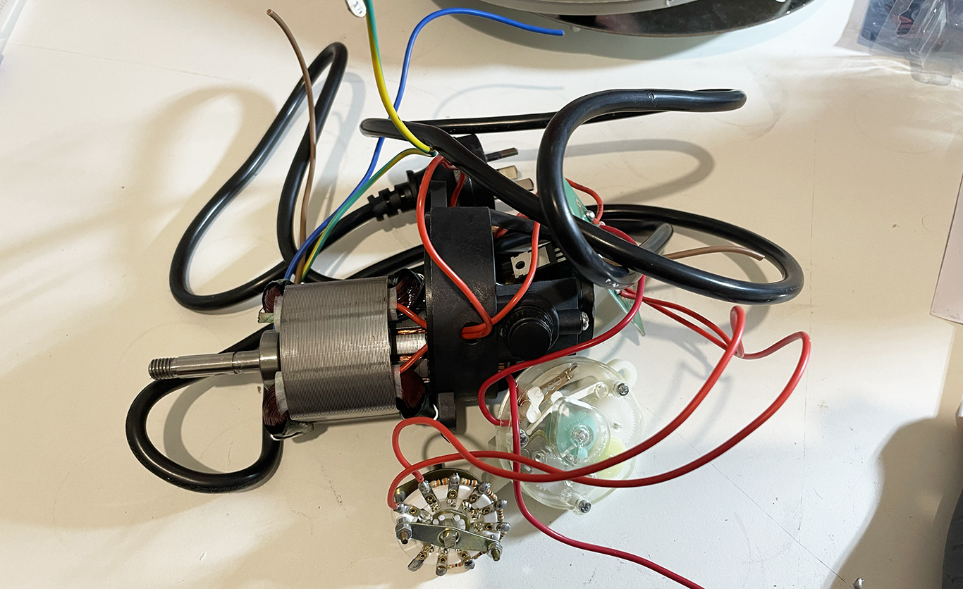
So it is as simple as possible, precisely what is expected at that price. It doesn’t really matter, though, because it is all going. I’m only keeping the case, the rotor and the motor mount.
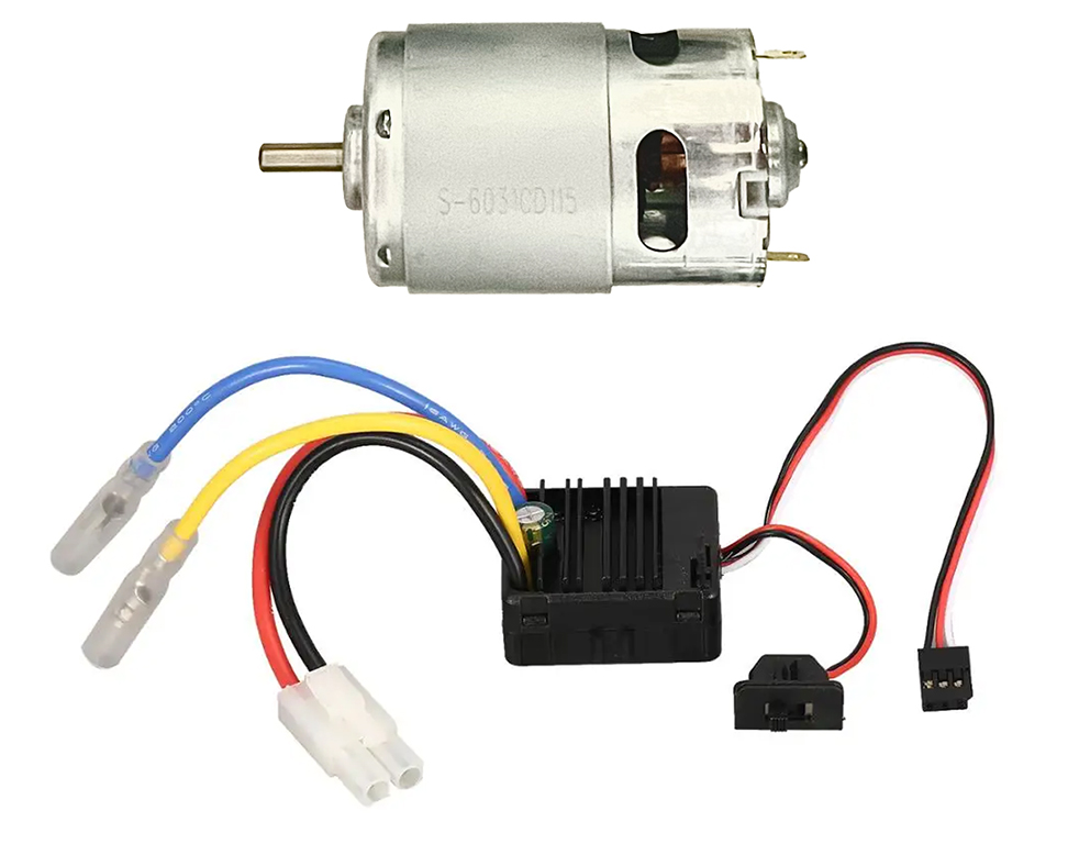
The first job is to replace the motor. I honestly don’t really like working with 240v, not just from a safety perspective but also because it limits the options. Interfacing a microcontroller to 240v requires a different approach, and because of that, there are fewer options, which tend to be costly. I did consider the control module from Kemo, but if you want to interface it with a microcontroller you need the DC Pulse Converter also. Instead, I used a 12v motor and Electronic Speed Controller (ESC) designed for hobby cars. The motor I’m using runs up to 9700 RPM and produces 6.5kg/cm of torque, more than enough to spin some cells. The ESC is a Hobbywing Quickrun WP 1060, which easily handles the current load, and I can use the standard servo interface using Pulse Width Modulation (PWM).
The new motor only has a 5mm shaft, whereas the original motor’s shaft is 8mm, so an adaptor will be required. I took a M6 x 65mm bolt and cut the head off, leaving 43mm to match the original shaft length. Drilled a 5mm hole down the centre for the motor shaft on the drill press and added a pin for the rotor.
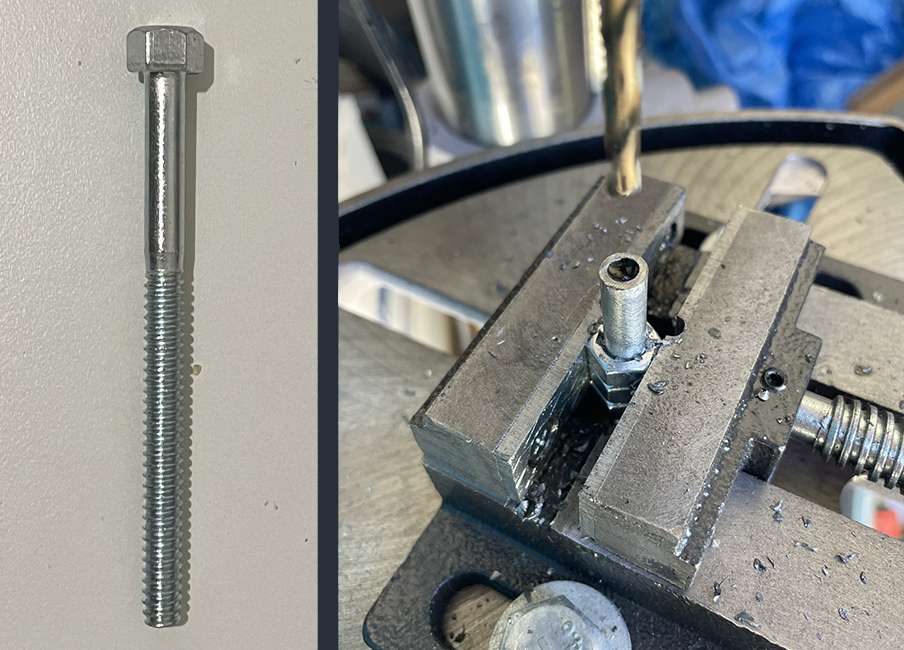
I also made a 2.5mm hole in the side for a worm screw, which was made from an M3 screw with the head cut off and a screwdriver slot cut with a Dremel. That secures it to the motor shaft, so there is no slipping.
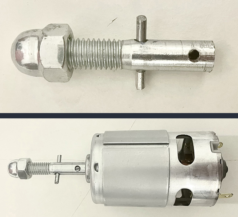
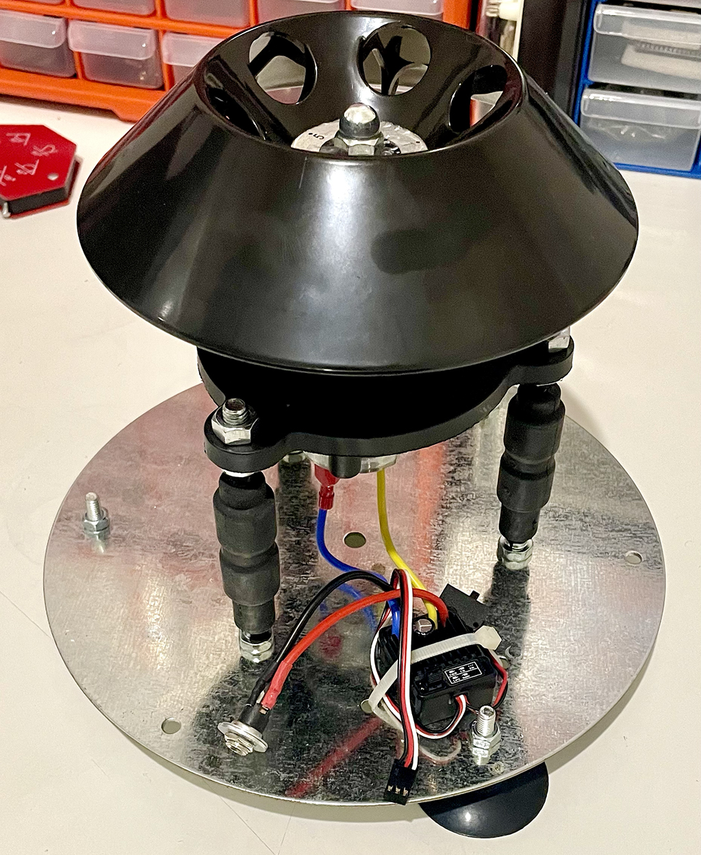
Next, I assembled the new motor, shaft, and controller on the original mount. Attached the rotor, and now have a fully controllable drive system.
A word of caution when drilling the hole down the centre of the bolt, it needs to be straight. Like, really straight. Even a 1/0th of a degree off, and it will vibrate uncontrollably. So here are a few tips:
- Make sure your drill press table is level, there are plenty of videos on YouTube showing how to do this.
- After cutting the head off the bolt, place the unthreaded end in the drill press’s chuck with 2-3 nuts on the other end.
- Lower the chuck until the nuts are in the vice. Tighten the vice and undo the chuck. Now, the centre of the chuck should align to the centre of the bold.
- USE A CENTRE BIT to start the hole. A normal drillbit will flex, and you will have no chance of getting the hole straight.
That’s the motor finished so we’ll design and build the controller in the next part. Stay tuned!